A 2007 Nissan Pathfinder arrived stuck in low range 4x4 with C1154, C1156, and U1000 codes stored after recent bodywork. The technician found that after an attempt to manually shift the transfer case, the drive system refused to leave 4LO. Basic ground checks had been completed, the CAN signal at the OBD port appeared normal, and connectors at the ABS module, neutral switch, and under the left sill all looked visually intact.
Thermal damage to the wiring harness
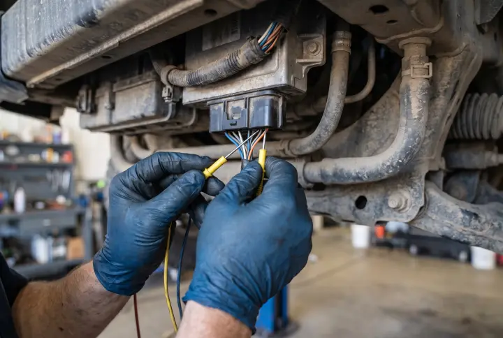
Our diagnostic platform ranked thermal or mechanical damage to the body wiring harness as the most likely cause, at 85 percent probability. In the Nissan Pathfinder R51, the main electrical harnesses connecting the front of the vehicle, the 4WD control module, airbag unit, ABS sensors, and transmission are routed through the interior of the left and right sills as well as the floor crossmembers.
During body welding on the sills or chassis mounts, it is highly common for protective tubing to burn and wire insulation to melt. This can create a short circuit between the twisted CAN bus pairs (CAN-H and CAN-L) or short them to the chassis ground. The result is a total loss of CAN network integrity, triggering the U1000 code. Without the network, the Park/Neutral Position signal cannot reach the modules (C1154), and communication with the steering angle sensor drops (C1156). Because the Transfer Case Control Module (TCCM) strictly blocks shifting out of 4LO unless it receives a confirmed neutral signal, the drive system remains locked. Recommended tests include a physical inspection of the harness near the welding sites, measuring insulation resistance of the CAN lines to ground, and checking the total CAN termination resistance at the OBD port.
Overvoltage failure of the steering angle sensor
Ranked at 78 percent probability was overvoltage damage to the steering angle sensor (SAS) caused by welding currents. If body welding is performed without properly disconnecting the battery or with poor ground clamp placement, high currents travel through the chassis and steering column.
The SAS contains sensitive microelectronics and its own CAN transceiver. A voltage spike can easily destroy its input circuits. A damaged SAS will either stop communicating entirely (triggering C1156 in the ABS module) or generate corrupted frames that flood the network (triggering U1000). To confirm this, isolate the SAS by disconnecting it from the CAN network and observing if the rest of the bus recovers. Technicians should also verify power and ground at the SAS connector and check for live steering angle data in the ABS module.
Power supply shorts and TCCM safety lockout
A blown fuse for the 4WD, ABS, or SAS circuits was ranked next at 72 percent probability. A momentary short to ground during bodywork can easily blow a fuse in the passenger footwell or the IPDM E/R module in the engine bay. If the TCCM loses power, it immediately stops responding on the CAN bus, causing the ABS module to log missing data codes. Diagnostic steps here include testing for 12V continuity across the relevant fuses and checking the fusible links at the battery.
Even if power is restored, the TCCM itself operates on a strict safety logic, ranked at 65 percent probability as a contributing factor. It demands a confirmed neutral signal to disengage the transfer case motor from 4LO. With active C1154 and U1000 codes, the TCCM interprets the vehicle state as unsafe and entirely disables the shift motor. Testing the TCCM requires reading its internal fault codes, checking the resistance values of the 4x4 rotary selector, and verifying power delivery directly to the transfer case servomotor.
Diagnostic takeaways
When multiple network and signal codes appear simultaneously following chassis welding, always investigate the physical integrity of the wiring near the repair zones before condemning individual modules. A thorough visual inspection of the sills and a network isolation test on the steering angle sensor are the most direct ways to locate the fault on this platform.