A 2014 Audi A6 rolls into the bay with a simple complaint of misfiring and running rough, but the scanner pulls eleven fault codes across four different emission and fuel systems. The vehicle, a 4G IV model from the Swedish market, presented a list that looked like a complete control module meltdown. We had P2425, P2426, P0201, P0202, P0203, P2463, P2002, P2032, and P2049, with duplicates on the DPF and EGT codes.
When a ticket just says the car misfires and runs rough, and you pull a list like that, the instinct is often to clear the codes and see which one comes back first. But in the diagnostic platform we build, we see how these systems interact. This was not a random collection of failures. It was a targeted electrical breakdown across the 3.0TDI V6 CRTE engine.
Isolating the Driveability Complaint
The most pressing issue was the immediate driveability problem. The customer felt the misfire, and codes P0201, P0202, and P0203 mapped exactly to that symptom. These codes indicate electrical faults in the fuel injector circuits for cylinders 1, 2, and 3.
On this specific engine with piezo injectors, the wiring harness routing is a known stress point. The cables are subjected to immense heat and oil exposure over time, and the connectors are prone to losing connection or corroding. When a whole bank of injectors throws electrical fault codes simultaneously, you are almost always looking at a harness issue rather than three injectors failing on the exact same day.
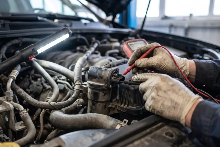
The diagnostic path we routed for this was strict. First, a visual inspection of the injector wiring and the connectors themselves. Second, a continuity test of the injector lines directly from the engine control unit to the injectors. Finally, a resistance measurement of the injectors to rule out an internal short.
Tracing the Exhaust Gas Recirculation Codes
Once the fuel delivery side is mapped out, the focus has to shift to the emissions equipment. The scan showed P2425 for an open circuit and P2426 for a low signal on the EGR cooling valve.
This is where cascading failures begin. The engine control module detected that the control circuit for the EGR cooling valve was either broken, shorted, or suffering an internal electrical fault. When this valve fails, it prevents the effective cooling of the recirculated exhaust gases. Hotter EGR gases lead directly to increased soot formation in the intake and exhaust tracts. This elevates combustion temperatures and heavily contributes to downstream diesel particulate filter problems.
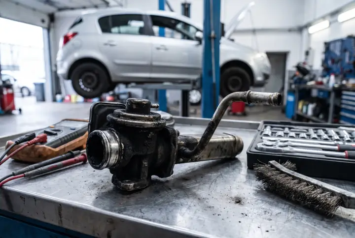
To isolate this, the required steps are a visual inspection of the EGR cooling valve harness and connector, followed by measuring the voltage at the connector, and finally a resistance check of the valve coil itself.
The AdBlue and SCR System Breakdown
Further down the exhaust stream, we had code P2049. This indicates a high signal at the reduction agent injector, specifically Bank 1, Unit 1.
A high signal in this circuit usually points to a short to positive, an open circuit, or wiring damage. However, on diesel vehicles equipped with selective catalytic reduction systems, there is a physical reality that electronics often ignore. AdBlue fluid loves to crystallize. When it crystallizes around the injector connector, it creates a bridge that causes electrical shorts and completely disables the SCR system. This failure disables emissions control, spikes NOx output, and can actively prevent the DPF from running a regeneration cycle.
We recommended a visual inspection of the AdBlue injector wiring and connector, looking specifically for that white crystalline buildup. From there, a continuity and short test of the circuit, and a resistance measurement of the AdBlue injector are necessary to confirm the electrical integrity.
The Regeneration Blockade
The final piece of the puzzle involved the diesel particulate filter. The scan returned P2032, indicating a low signal from Exhaust Gas Temperature Sensor 2 on Bank 1. We also had P2463 and P2002, which are direct DPF restriction and efficiency codes.
EGT Sensor 2 is located just after the diesel particulate filter. Its entire job is to monitor the temperature of the filter to control the active regeneration process. A low signal means an open circuit, a short to ground, or a dead sensor. If the engine control module cannot see the temperature of the exhaust gas exiting the filter, it will permanently block any attempt to regenerate. The soot from the failing EGR cooling valve and the misfiring injectors piles up in the filter, and because of the blind EGT sensor, the car can never clean it out.
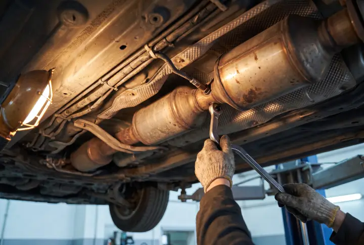
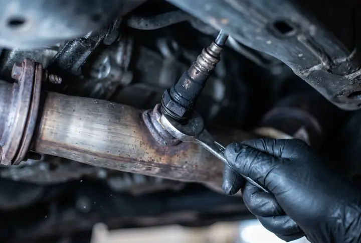
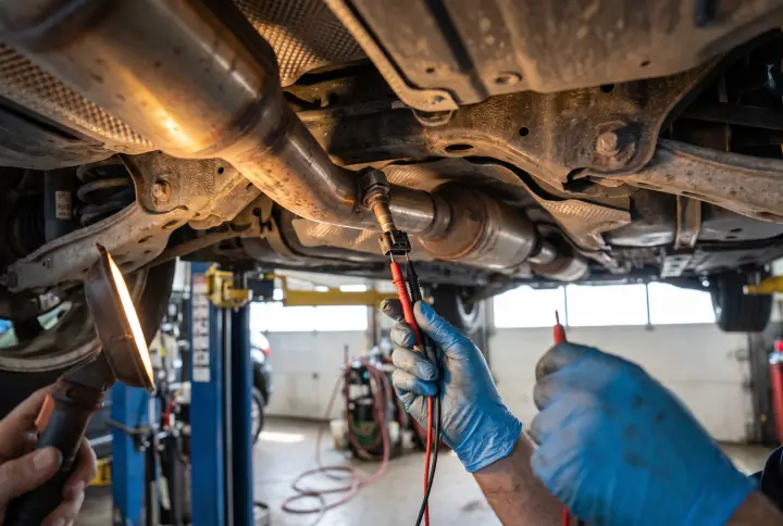
The fix requires inspecting EGT Sensor 2 and its wiring beneath the vehicle, running a continuity test on the harness, and measuring the sensor resistance.
Breaking the Chain
Modern diesel diagnostics are rarely about a single failing part. An electrical fault in the injector harness causes a misfire. A failed EGR cooler cooks the exhaust. A shorted AdBlue injector stops emissions processing. A blind temperature sensor lets the whole system choke on soot.
Do you see these cascading codes on the V6 TDI platforms in your own bays, and do you tackle the driveability codes before the emissions faults?