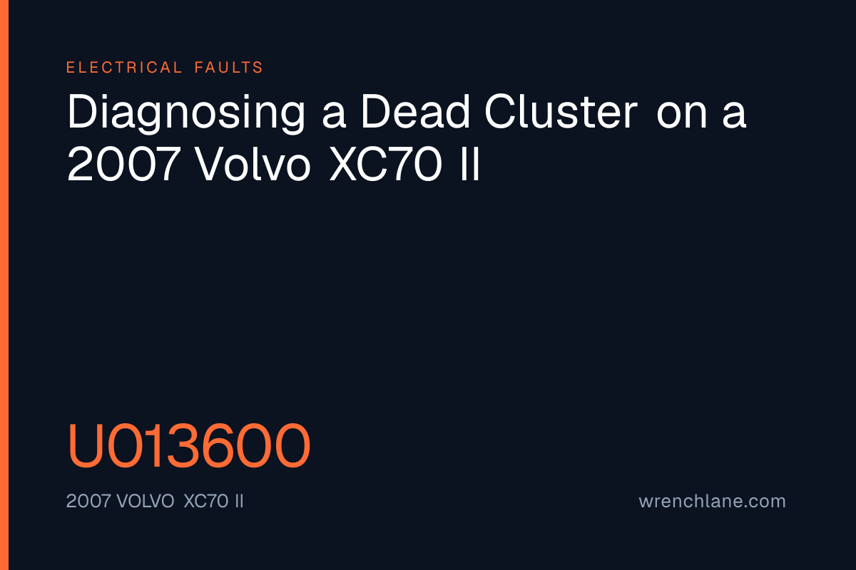
A 2007 Volvo XC70 II rolled in with a completely dead instrument cluster and info display, throwing just two communication codes: U013600 and U015100. The technician simply noted that the combo instrument and info display were completely extinguished. When we analyze this specific combination of U-codes and the dead cluster symptom in our own data, it maps out a clear diagnostic path based on actual failure rates.
MS-CAN Bus Interruption
An interruption or short circuit in the MS-CAN bus network ranked as the most probable cause at 75 percent likelihood. On the Volvo P3 platform, the Driver Information Module (DIM), Infotainment Control Module (ICM), and the Supplemental Restraint System (SRS) all connect to the medium-speed CAN bus operating at 125 kbps. The Central Electronic Module (CEM) terminates and administers this bus.
If a short occurs between CAN-High and CAN-Low, or if either line shorts to chassis ground or battery voltage, the entire bus communication collapses. Common culprits include wire chafing behind the center console or damaged harnesses. Because the DIM and ICM rely on CAN wake-up messages to turn on, a bus failure leaves both screens black, especially during a cold start. The CEM logs the U015100 code due to missing responses from the SRS module. A severe bus collapse overloads the CEM gateway function, causing timeouts on other network branches and triggering the U013600 code for the Rear Differential Electronic Module (DEM).
The suggested testing procedure begins with measuring the resistance of the MS-CAN terminating resistors with the system powered down. Technicians should then measure the voltage of CAN-High and CAN-Low against chassis ground with the ignition on, followed by an oscilloscope waveform analysis of the data bus.
Voltage Supply and the CEM Relay
The second most likely fault, ranked at 70 percent, pointed to a voltage supply failure or a faulty ignition relay inside the CEM. On the XC70 II, the CEM sits under the passenger side glovebox and distributes all ignition and instrumentation power. Both the DIM and ICM require constant battery voltage at Terminal 30 and an ignition-activated supply at Terminal 15.
An internal relay or electronic power distribution circuit in the CEM can fail. This becomes particularly noticeable during a cold start, when lower temperatures shrink the contact surface of worn relay contacts or cracked solder joints. Without the Terminal 15 voltage, the DIM and ICM never wake up. Since the CEM acts as the central gateway, an internal board failure stops it from forwarding information between networks, breaking communication with both the SRS and DEM modules.
To verify this, the testing path directs the technician to measure voltage and continuity across the DIM and ICM fuses in the CEM. The subsequent steps involve measuring the constant and ignition voltage at the DIM connector, and checking for a voltage drop across the CEM ignition outputs during a cold start.
Internal Hardware Failure in the Cluster
An internal hardware failure in the DIM came in at a 65 percent probability. The instrument cluster on this generation of Volvo is sensitive to micro-cracks in the printed circuit board solder joints. These cold solders typically form around the main processor unit and the internal voltage regulation circuits.
Hundreds of thousands of thermal cycles take their toll on the board. During a cold start, the metal and solder contract, causing latent micro-cracks to separate completely. The internal voltage regulation collapses and the panel goes black. If the DIM suffers an internal short or processor crash, it stops sending and acknowledging network messages on the MS-CAN, which disrupts the ICM and generates the U015100 code for the airbag system.
Testing this requires verifying the internal boot process with a guaranteed external power and ground supply. Gentle heating of the DIM during a cold start serves as thermal provocation, followed by checking the internal 5V and 3.3V circuits on the board.
Moisture Intrusion at the A-Pillar
Finally, moisture damage or contact oxidation in the CEM carried a 60 percent likelihood. Water intrusion is a known issue on the P3 platform. Water often enters from the wiper cowl drains or leaking sunroof drain hoses near the A-pillar.
This water runs directly down the wiring harnesses and pools in the large multi-pin connectors of the CEM. Over time, this leads to heavy galvanic corrosion and oxidation on the contact pins. The corrosion can short the MS-CAN and HS-CAN buses, or sever the power supply pins for the displays. The cluster dies, and modules across different bus branches drop out.
The diagnostic path here starts with a visual teardown and inspection of all CEM connector pins. The technician must also check for moisture in the carpets and insulation under the glovebox, and measure the voltage drop across the CEM connections.
Spotting the Network Collapse
When a vehicle presents with dead interior displays and communication codes across different network branches, the root cause usually sits at the central gateway or the power distribution feeding it. Do you often see water intrusion causing these cascade failures on the P3 platform in your own bays? Let me know.