A 2014 Opel Vivaro B arrived with a cruise control and limiter warning, throwing code P0564 with sub-codes for high voltage and out-of-range voltage. The technician noted that these specific readings appeared when pulling the codes and interacting with the cruise control system.
The Resistor Ladder Network
Our diagnostic platform ranked a defective steering wheel button module as the most likely cause, at a 75 percent probability with medium severity. On the Opel Vivaro B, which shares its architecture with the Renault Trafic III, the cruise control buttons operate as a resistor ladder network. The engine control module supplies a 5V reference voltage across the circuit and reads the resulting voltage drop to determine which button was pressed.
When a micro-switch develops internal contact failure or oxidation, pressing the button creates a microscopic open circuit. The ECM interprets this lack of voltage drop as the full 5V, triggering the high voltage or open circuit codes.
Clock Spring Fatigue
A loose connection or break in the clock spring was ranked next at 65 percent. The flat ribbon cable inside the clock spring is a known wear item that transfers signals from the rotating steering wheel to the fixed column.
Mechanical pressure on the steering wheel spokes or tiny movements in the hub can cause a fatigue crack in a copper trace to open completely. This temporary break in the circuit perfectly matches the open circuit and out-of-range voltage conditions recorded by the technician.
Wiring Harness and ECM Inputs
Moving further down the circuit, a wiring harness fault in the steering column was ranked at 35 percent. Cables can chafe against sharp metal edges or suffer stress during column adjustments, leading to high transition resistance.
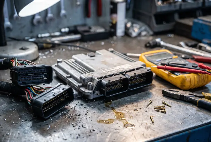
An internal ECM hardware fault in the analog input circuit was assigned a 15 percent probability. If a transient voltage spike damages the internal pull-up resistor or the analog-to-digital converter channel, the ECM will register a constant open state even if the external buttons and wiring are perfectly healthy.
Diagnosing the Circuit
The most efficient path is to start with live data in a diagnostic tool, watching the voltage level change as each button is activated. If the reading is stuck at an open state, technicians should measure the resistance directly across the button module pins while pressing them. A continuity test through the clock spring from lock to lock will then confirm if the ribbon cable is failing, allowing the shop to isolate the physical component before investigating the wiring harness or ECM.