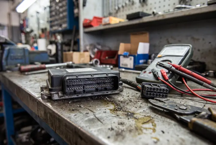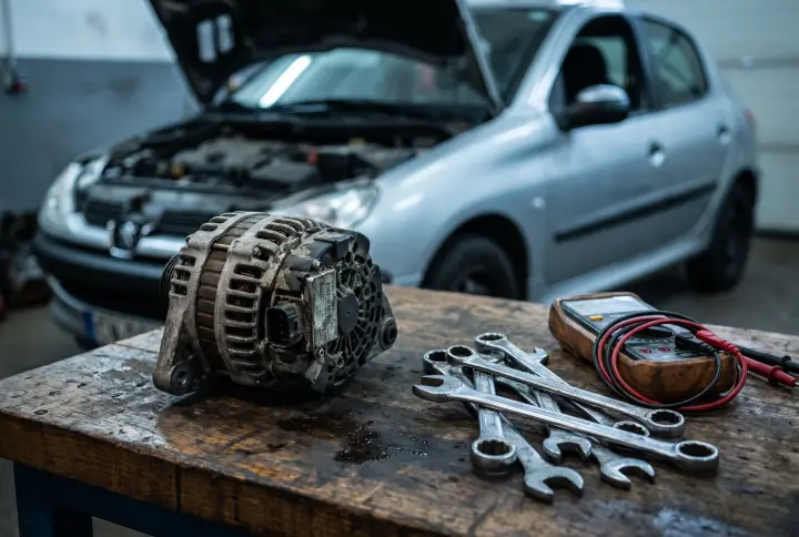
A 2010 Peugeot 508 (W2) rolled in with a P2711 code and a note about mismatched gear signals. The technician found a lack of coherence between the hardwired drivetrain status and the CAN data from the automatic gearbox. This is the sort of fault that can easily stall a bay. The transmission control module says one thing, the physical sensors report another, and you are left to figure out which side of the system is lying.
When a vehicle logs an unexpected mechanical gear disengagement, the instinct is often to look straight at the physical gearbox. However, the exact wording of this diagnostic note points to a communication conflict. The system is receiving contradictory information.
The primary suspect: ECU to TCM communication
Our engine ranked wiring harness damage and connector corrosion as the most likely cause, sitting at a 90 percent probability with a medium severity rating. The diagnostic information explicitly states a lack of coherence between the wire information on the status of the drive train and the CAN information from the automatic gearbox. This strongly indicates a communication breakdown or conflicting data.
The physical wiring harness segments leading to the transmission and its various sensors are constantly exposed to a harsh environment. The lines running to the transmission range sensor, the input speed sensor, and the output speed sensor are highly susceptible to fatigue. We also see frequent chafing and corrosion at the electrical connectors bridging the engine control unit and the transmission control module.
The vibrations inherent to diesel engines can accelerate these physical wiring issues. Over time, this leads to intermittent signal loss, high resistance, or complete degradation of the circuit. The engine and transmission modules eventually register an unexpected mechanical gear disengagement. This problem specifically affects the integrity of the differential voltage lines within the CAN bus or the direct sensor feedback paths.
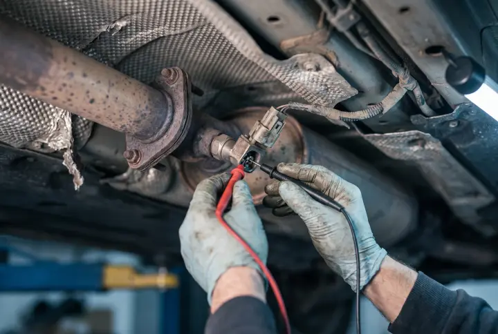
Proving this requires getting hands on the wiring. The initial diagnostic step is a visual inspection of the harness and the connectors. You are looking for obvious pin fitment issues, green crust, or rubbed wires. From there, a CAN bus resistance test is necessary to ensure the network terminates correctly and the lines are not shorted. Live data monitoring of the communication parameters will help identify if packets are dropping while the vehicle is running.
When hydraulic failure triggers a digital code
The mechanical side of the transmission cannot be ignored, even when the code complains about data coherence. We ranked a malfunction in the hydraulic valve body, commonly called the mechatronic unit or hydroblock, at a 70 percent probability with a high severity.
The hydroblock is critical for directing transmission fluid to engage and disengage the gears. It contains numerous internal passages, pistons, and shift solenoids. If those passages become blocked by debris, or if individual solenoids fail electrically or mechanically stick, the transmission will fail to maintain the commanded hydraulic pressure. Without pressure, the transmission cannot hold a gear.
This physical disengagement or slippage is detected by the transmission control module, which then logs the P2711 code. The lack of coherence arises when the module commands a specific gear over the CAN network, but the physical components monitored by wired sensors fail to respond correctly.
Closely related to this is the condition of the transmission fluid, which ranked at a 50 percent probability with a high severity. Transmission fluid is essential for maintaining hydraulic pressure, lubricating internal components, and dissipating heat within the gearbox. The fluid may be low due to leaks, or severely degraded and contaminated from prolonged use.
Insufficient fluid levels directly lead to a lack of hydraulic pressure, preventing proper gear engagement. Contaminated fluid, especially if it is burnt or laden with metallic particles, can cause those shift solenoids to stick. It accelerates wear on the clutch packs and blocks vital hydraulic passages within the valve body. While the code description emphasizes a coherence issue, underlying hydraulic problems often manifest with these exact symptoms.
Testing for these mechanical and hydraulic causes starts with a transmission fluid level check and a fluid condition assessment. You want to inspect the fluid for metallic debris and signs of severe degradation. During operation, live data monitoring of the commanded gear versus the actual gear will highlight slippage. Finally, shift solenoid resistance testing will verify the electrical health of the actuators.
Internal module failure and software corruption
The brain of the automatic transmission can also be the source of the conflict. An internal failure or software corruption within the transmission control module ranked at a 60 percent probability with a medium severity.
The control module processes sensor data, makes decisions about gear shifts, and communicates with other vehicle modules via the CAN bus. Internal component failures within the module itself can completely disrupt this process. We see circuit board cracks, failed voltage regulators, and damaged memory cells causing the module to misinterpret sensor data.
Corrupted or outdated software calibrations can also cause the module to send incorrect shift commands or report erroneous gear status back to the engine control unit. This directly manifests as the described lack of coherence. The internal state of the module, or the gear status it reports to the network, conflicts with the raw sensor data it receives via its wired connections.
To test the module, you need to check for transmission specific U-codes that indicate internal faults or broader network dropouts. You must also perform thorough power and ground checks at the module itself. Bad grounds are notorious for causing strange internal processing errors. Finally, check if a software update or relearn procedure is available for the module, as a flash can resolve calibration errors that mimic hard failures.
Tracking the coherence faults
The diagnostic platform we build relies on our own data to map out these specific relationships between trouble codes, network data, and physical transmission components. We see these network coherence faults frequently across different manufacturers.
Does your workshop regularly encounter this specific pattern, where the physical gear state and the network data tell two completely different stories?