O₂ Sensor Explained: Function, Diagnostics, Codes & Wideband vs. Narrowband
O₂ Sensor – Function, Diagnostics, Trouble Codes & Wideband vs. Narrowband
The oxygen sensor (lambda sensor) is one of the most critical feedback devices in any modern engine. It ensures the air-fuel mixture stays near the ideal stoichiometric ratio (λ≈1), keeping performance, emissions, and fuel economy in balance.
📑 Table of Contents
- What does an O₂ sensor do?
- Upstream vs. downstream sensors
- Why do O₂ sensors have heaters?
- Narrowband vs. Wideband
- How to check sensor function
- Measuring wideband & pump current
- Common OBD-II codes
- Quick troubleshooting checklist
- FAQs
- Wrap-up
What does an O₂ sensor do?
Most O₂ sensors are based on zirconium dioxide (ZrO₂). Inside, a Nernst cell compares oxygen levels in the exhaust to outside air. The resulting electrical signal tells the ECU whether the mixture is rich or lean.
- Narrowband sensors switch voltage rapidly around ~450 mV.
- Wideband (UEGO/AFR) sensors use an additional pump cell to keep the Nernst cell at ~450 mV. The ECU measures the pump current, which is proportional to lambda (λ). This provides a linear AFR reading across a wide range.
Upstream vs. downstream sensors
- Sensor 1 (upstream, before the catalytic converter): Provides real-time feedback for fuel trim. A healthy narrowband sensor will switch rapidly above and below 450 mV.
- Sensor 2 (downstream, after the cat): Monitors catalyst efficiency. It should be more stable and slower-moving. If S2 begins to mirror S1, the catalyst may be degraded and trigger P0420/P0430.
Why do O₂ sensors have heaters?
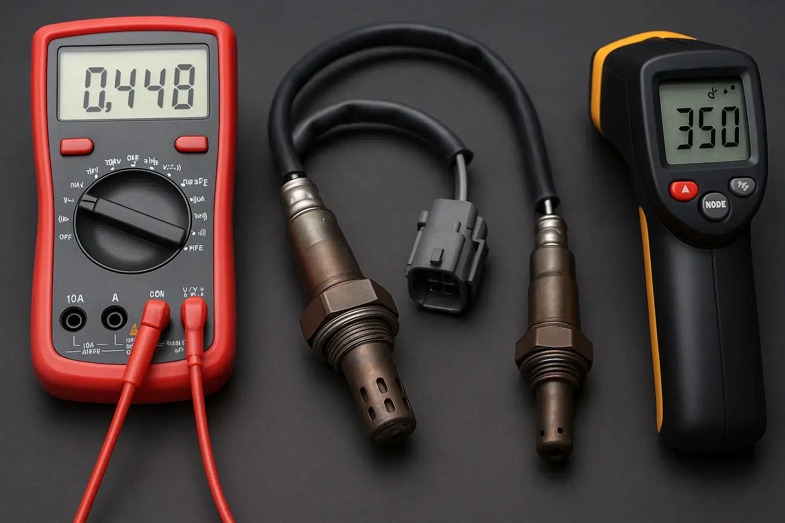
O₂ sensors must reach at least ~350 °C to function properly. Built-in heating elements bring them up to temperature quickly, reducing cold-start emissions and allowing the ECU to enter closed-loop faster.
Common heater-related trouble codes include P0135, P0141, P0161.
Narrowband vs. Wideband
| Feature | Narrowband (zirconia) | Wideband (UEGO/AFR, e.g. Bosch LSU 4.9) |
|---|---|---|
| Output | Switching voltage (~0.1–0.9 V) | Pump current, reported as λ or AFR (0–5 V output) |
| Range | Accurate only near λ≈1 | Linear, accurate across rich/lean |
| Wires | 1–4 wires | 5–6 wires (signal, pump, reference, heater, calibration) |
| Use | Basic fuel trim, post-cat monitoring | Precise AFR measurement, modern ECUs, tuning |
How to check sensor function
With a scan tool
- Sensor 1 should oscillate rapidly lean/rich once warm.
- Sensor 2 should be smoother and more stable.
- Check fuel trims (STFT/LTFT). Large deviations may point to O₂ faults or exhaust leaks.
- Catalyst efficiency monitors will flag if S2 mimics S1.
With a multimeter/oscilloscope (narrowband S1)
- A healthy sensor cycles between ~0.1–0.9 V several times per second. A “stuck” or sluggish trace indicates aging.
Heater circuit
- Verify resistance across heater pins and check power/ground. Common codes: P0030, P0135, P0141, P0161.
Exhaust leaks
- Leaks before S1 pull in fresh air, causing false lean readings and unstable trims.
Measuring wideband & pump current
Unlike narrowband sensors, wideband O₂ requires a controller circuit (OEM ECU or external wideband module).
- Pump current is the actual measurement. It flows in the milliamp (mA) range (typically –2 mA to +2 mA depending on mixture).
- The ECU or controller keeps the Nernst cell at ~450 mV by regulating this current.
- Direct measurement with a normal ammeter is not practical — the current is small and fast-changing. Instead, the controller measures it via a shunt resistor.
- Most wideband controllers convert pump current into a linear 0–5 V AFR output or a direct λ value for scan tools.
⚡ Pump Current Explained
- Lean exhaust → current flows in one direction.
- Rich exhaust → current flows in the opposite direction.
- The size and direction of this current tell the ECU exactly how much oxygen is present.
In practice, mechanics will read AFR or λ from scan data or a wideband gauge, rather than measuring raw pump current.
Common OBD-II codes for O₂/AFR sensors
| Code | Description |
|---|---|
| P0130 / P0150 | O₂ sensor circuit fault, Bank 1/2 Sensor 1 |
| P0133 / P0153 | Slow response, B1/B2 S1 |
| P0134 | No activity, B1 S1 |
| P0135 / P0155 | Heater circuit fault, S1 (B1/B2) |
| P0140 | No activity, B1 S2 |
| P0141 / P0161 | Heater circuit fault, S2 (B1/B2) |
| P2195 / P2197 | Sensor stuck lean |
| P2196 / P2198 | Sensor stuck rich |
| P0420 / P0430 | Catalyst efficiency below threshold (B1/B2) |
Quick troubleshooting checklist
- Check heater power/ground if heater codes are present.
- Compare S1 vs. S2 live data. If both look similar, suspect catalyst issues.
- Test the exhaust system for leaks.
- Look for sensor contamination (oil, coolant, silicone).
- Replace sensors that respond slowly even with no leaks present.
FAQs
Should the downstream sensor (S2) switch like the upstream (S1)?
No. A healthy catalytic converter will keep S2 much more stable.
What voltage should I see from a narrowband sensor?
Expect ~0.1–0.9 V swings in closed loop.
How hot does the sensor need to be?
Around 350 °C, which is why heaters are built in.
Can I measure pump current directly?
Yes in theory, but in practice no. The currents are in the mA range and controlled inside the ECU. Use a scan tool or wideband controller that reports AFR or λ, which is derived from pump current.
Wrap-up
O₂ sensors are small but have a massive impact on performance, fuel economy, and emissions. Knowing how they work – and how to test them – helps workshops avoid misdiagnosis and fix cars faster.
👉 Tip: With WrenchLane you can search multiple O₂-related DTCs at once and get targeted troubleshooting guides, including TSBs and step-by-step fixes.